Skip to content
DevMeme
6682 of 7435
Signal Integrity Is a Myth Propagated by Wire Companies: DIY Serial Connector
Hardware Post #7325, on Oct 23, 2025 in TG

Signal Integrity Is a Myth Propagated by Wire Companies: DIY Serial Connector

Why is this Hardware meme funny?

Level 1: Plug and Pray

Imagine you need to water your garden but you don’t have the proper hose connector to attach your hose to the faucet. In a pinch, you shove the hose onto the faucet as best you can and tie a rag or rubber glove around it to hold it together and stop the leaks. Then you turn on the water, and to your surprise, a trickle comes out the other end – it’s working, sort of! You grin and declare, “Ha, who needs fancy connectors? Water-tight seals are just a myth made up by plumbing companies!” Now, anyone watching this would laugh because it’s obvious you’re doing a sketchy setup and just hoping it holds. In reality, without a proper connector, every slight bump could send water spraying everywhere, and you’re probably losing pressure and getting the floor wet. But you’re joking that some kind of garden hose fairy is helping you out, keeping it all working despite the clearly bad setup.

That’s exactly what this meme is about, but with a computer’s communication wires. Someone basically plugged in wires haphazardly and jokingly said “signal integrity” (the equivalent of water-tight integrity for electrical signals) is just a fake idea sold by wire makers. It’s funny because we all know they’re getting by on luck. It captures that feeling of doing something the “wrong” way and praying it doesn’t fall apart. The humor comes from pretending there’s a magical helper – the UART fairy – who will make the signals go through cleanly, even though the wiring is a mess. It’s like saying rules don’t matter as long as you believe (and have a bit of glove to insulate)! Everyone deep down knows that’s silly – the proper way exists for a reason – but seeing someone say it out loud in such an absurd scenario makes it a good laugh. It’s a reminder of those times we’ve all jerry-rigged a solution and crossed our fingers, hoping for a little everyday tech magic to save the day.

Level 2: Flying Leads 101

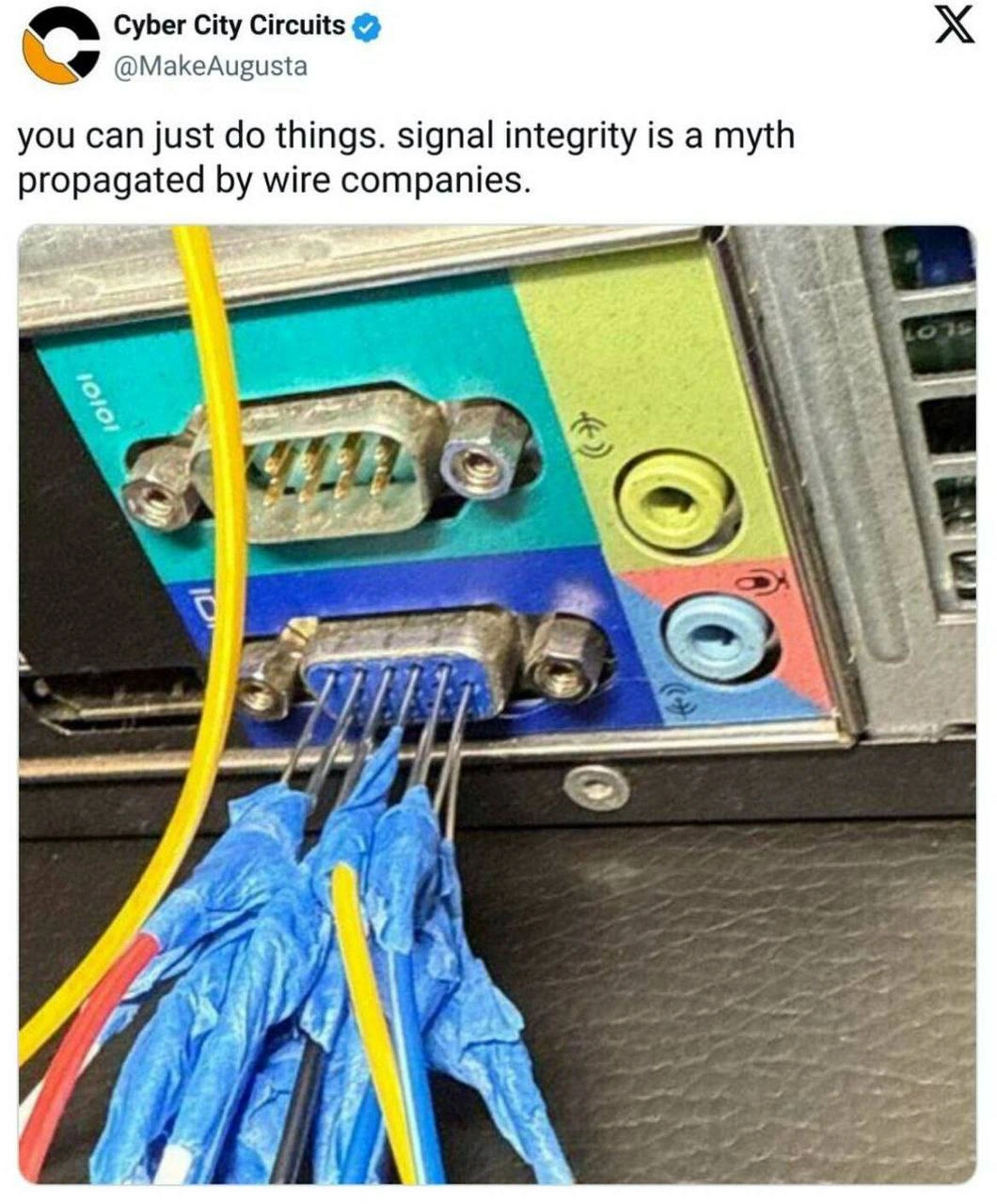
Let’s break down what’s going on in this meme for those newer to hardware and EmbeddedSystems. In the image, you see the backside of a desktop PC. There’s a colorful plate where various ports live: blue VGA for video, some round audio jacks, and notably a small blue connector with 9 metal pins – that’s a DB-9 port, which is typically used for old-school serial communication (RS-232 standard). If you’ve heard of a “COM port” or seen a serial port on older equipment, this is it. Normally, you’d plug a matching connector into it, which has 9 corresponding sockets. That connector would terminate to a cable, and that cable would go to your device or another computer. Each pin on the DB-9 carries a different signal (like transmit data, receive data, ground, etc.).

Now, what happened here is that someone didn’t use a standard DB-9 plug at all. Instead, they took individual jumper wires (the kind with little pin connectors or bare ends that you use on breadboards and Arduino projects) and shoved them directly into the port’s pins. This is sometimes called using flying leads – basically loose wires flying between connections without any sturdy connector holding them. Each of those colored wires (red, yellow, blue, black) is connected to one of the serial port pins, presumably to link to whatever device or circuit they’re trying to communicate with. The reason you usually avoid this is that it’s very easy for those wires to slip off or not make good contact, and also the pins could touch each other accidentally.

You might notice each wire/pin in the photo is surrounded by something blue and crinkly – that’s actually pieces of a nitrile glove (the disposable gloves people wear when soldering or handling chemicals). Why on earth is that there? Think of it as improvised electrical tape. The person likely cut or tore bits of a glove and wrapped them around each metal pin to keep them isolated. This prevents short circuits (a short is when two conductive parts touch when they shouldn’t, which can cause all sorts of problems, from data errors to fried components). It’s a hack, but it demonstrates the person knew the risk of bare pins touching. Ideally, you’d use heat-shrink tubing or actual wire insulation, but hey, in a pinch, a glove can work as an insulator – nitrile is rubbery and doesn’t conduct electricity, so it’s serving as a DIY insulation sleeve. It’s the same idea as wrapping a wire in electrical tape, just much clumsier/funnier to see.

Let’s explain signal integrity in simpler terms. When we send data as electrical signals (especially high/low voltages for binary 1s and 0s), we want the signal that arrives at the other end to look like the signal that was sent – nice and clean, a proper square wave switching between voltages at the right times. If the connection is bad or the wiring is sloppy, the signal can get distorted. Distortion might mean the voltage doesn’t reach a full high or low, or it might bounce around (ringing), or it might pick up extra noise (random electrical interference). Imagine trying to talk to a friend on the phone, but there’s static or echo – that’s analogous to poor signal integrity for electrical signals. The friend’s voice is like the data, and the static is like noise. In digital terms, too much noise can make a 1 bit look like a 0 bit or vice versa. UART communication (that’s the type of serial communication happening over RS-232) is particularly simple: it’s just bits being sent one after another with no fancy error correction. So if a bit gets flipped due to noise, the receiving end will just misinterpret that character. You’ll see weird symbols or wrong letters. For instance, if the device was trying to send the letter A but one bit got messed up, you might get a different letter or a garbled character on your screen.

Here’s a tiny example: suppose in an Arduino program you write:

Serial.println("Hello");
// On a good connection, the PC receives: "Hello"
// On this hacky connection, you might see: "H?llo" (some characters messed up)

The "H?llo" outcome happens because noisy or weak signals can cause the UART on the PC side to mis-read some bits. The ? represents an incorrect character that came through due to a bit flip or framing error. This is why proper wiring matters.

Now, why do cables and connectors help with signal integrity? Proper serial cables for RS-232 have wires of the right gauge, often twisted pairs or at least bundled and sometimes shielded. Twisted pair wiring means two wires (like your transmit and ground, or receive and ground) are twisted around each other along the length of the cable. This helps cancel out electromagnetic interference – any noise that affects one wire will also affect the other in a similar way, so the difference between them remains the same (that’s how Ethernet cables work too!). Shielding means there’s a foil or braided metal wrap around the wires which blocks external electric fields, kind of like a little safety blanket for the signal. In our meme scenario, the wires are not twisted, not shielded, just straight shot and even separating away from the PC’s ground reference as they dangle. This makes them susceptible to picking up interference (like a radio antenna). Also, the longer and more untamed a wire, the more it behaves like a little circuit on its own – it has resistance, capacitance, and inductance distributed along it. Those can filter or skew the signal if not accounted for. A designed cable keeps those properties in check. A handful of loose jumpers… does not.

What about crosstalk? That’s when one signal traveling through a wire leaks into another wire’s signal. It usually happens because of electromagnetic coupling: when a current flows in one wire, it creates a magnetic field, which can induce a current in a neighboring wire. In our case, if the yellow wire is carrying transmit data and right next to it the blue wire is carrying receive data, a strong change (a quick transition from 0 to 1) in one could induce a blip in the other. Crosstalk can cause interference, like you think you’re only sending out data, but your receive line picks up some of that and injects false bits, for example. In well-designed systems, related signals might be spaced out or twisted with ground to mitigate this. Here, it’s a free-for-all cluster of wires, so crosstalk is definitely possible.

Now consider EMI (Electromagnetic Interference). This is any external source of electromagnetic waves that might affect your circuit. It could be as simple as the buzz from a fluorescent lamp, the radio waves from a nearby WiFi router, or the electrical noise from a motor or a microwave. In a proper cable, the shielding and the controlled structure help keep external EMI from messing up your signal, and also prevent your signal from emitting EMI that might mess with other devices. But with four bare-ish wires out in the open, our little serial connection can both emit and receive interference freely. If someone were to, say, walk by with a walkie-talkie or if a motor kicks on nearby, those wires could pick up a burst of noise and the data could get corrupted at that moment. Conversely, the rapid on/off pulses of the UART signal could radiate into the environment – usually not enough to matter for regulatory concerns at this low speed and short length, but in principle it’s uncontained.

So why did this person do this, if it’s so potentially problematic? Likely, this was a quick debugging or prototyping move. Imagine you’re developing some LowLevelProgramming on a new gadget – say, writing firmware for a microcontroller – and you need to see debug messages. Many microcontrollers output logs or accept commands via a UART serial interface because it’s simple and universal. If your PC has an old-style serial port (or you use a USB-to-serial dongle), you need a way to connect it to the microcontroller’s TX/RX pins. Ideally, your device has a connector or you have an adapter cable. But if not, you might just grab some Dupont wires (another name for those common jumper wires) and make do. You connect TX on the device to RX on the PC, RX on the device to TX on the PC, and a common ground between them. That’s three wires at minimum. The meme picture shows four wires – likely TX, RX, GND, and maybe one more (possibly a control line or an additional ground/voltage reference). They’ve done exactly this: created a makeshift cable. It’s functional, not pretty.

For a newcomer, the laugh here comes from the blatant disregard of textbook advice. It’s like seeing someone use scotch tape to fix a leaky pipe and saying “waterproofing is a myth.” The experienced folks laugh because it’s obviously a joke – we know why good connections matter – but we also remember times when we jerry-rigged something similar and hoped for the best. HardwareTradeoffs often involve doing things “the right way” vs. doing them “right now.” This meme shows an extreme of the “right now” approach. The phrase about “wire companies” propagating myths is pure snark; in reality, those companies (and more so, the engineering community) established best practices like using proper connectors, keeping wires short, and ensuring signal integrity to save everyone from headaches. It’s not an evil plot – it’s just physics and reliability. But from a humor angle, pretending it’s all a scam sets up a funny scenario because it flips logic on its head.

If you’re a junior dev or just learning about EmbeddedSystemsAndIoT, take this meme as both a joke and a gentle caution. Yes, you can sometimes get away with these crazy hacks when experimenting – and it’s kind of a rite of passage to have a tangle of wires around your prototype at some point. But when things start acting weird or you need something bulletproof, remember that signal integrity is a real concern, not just a buzzword. Those tedious details about impedance and shielding have real consequences. The meme is funny because it knowingly ignores those rules, but part of why we find it funny is that we all know what usually happens if you truly ignore them (spoiler: scrambled data or no connection at all). In short, enjoy the laugh, but don’t actually throw out your good cables!

Level 3: The Big Wire Conspiracy

For the seasoned developer or engineer, this meme hits that perfect facepalm humor. The post’s text claims “signal integrity is a myth propagated by wire companies” – a cheeky one-liner that every hardware engineer reads with a smirk. We all know it’s dripping with sarcasm. The photo evidence is a PC’s serial port (the old RS-232 DB-9 port on the back, color-coded blue) being abused in a way that makes any Hardware professional cringe and laugh. Instead of a proper serial cable snugly screwed in, there’s a rainbow of loose jumper wires (red, yellow, blue, black) just jammed straight into the male pins of the connector. As a cherry on top, each pin/wire is individually wrapped with torn pieces of a blue nitrile glove – yes, a blue_glove_insulation hack – to keep them from shorting together. It’s a scene of utter OverEngineering absurdity (or rather under-engineering, in this case), the kind of kludge you create during desperate Debugging_Troubleshooting at 2 AM when the lab’s closed and you don’t have the right adapter.

Experienced folks are chuckling because they’ve been there. Maybe not with a nitrile glove, but who hasn’t used a bit of electrical tape, a folded paper shim, or some random plastic as an insulator in a pinch? It’s the classic HardwareHacks ethos: if it fits (even poorly) and works (even barely), do it. This meme exaggerates that ethos to comedic effect, basically saying just wing it and trust the “UART fairy”. The "UART fairy" is an imaginary benefactor of bad practices – a mythical creature that blesses your sketchy wiring so that bytes still miraculously get through. Every senior engineer knows no such fairy exists; instead, there’s Murphy’s Law lurking, waiting to flip a bit or jiggle a wire loose at the worst possible moment. But the joke taps into that tiny hopeful voice we’ve all had when doing something questionable: “Maybe, just maybe, it’ll work... right?”

The humor also comes from the faux conspiracy claim that “wire companies” invented the concept of signal_integrity to sell fancy cables. This is poking fun at how juniors sometimes roll their eyes at meticulous wiring rules, or how management might balk at the cost of quality cables. It’s like saying “Twisted pair Ethernet cables with shielding are just a scam; I could’ve run Gigabit over spaghetti if Big Cable didn’t brainwash me.” 😏 Seasoned devs recognize the satire – we’ve spent hours tracing a bug only to find out it was the dodgy cable or a poorly crimped connector. In fact, “check the cable” is practically a mantra in hardware debugging. So claiming cables don’t matter is hilariously audacious. It’s humor through bold reversal: taking a true concern (signal integrity) and dismissing it with an absurd justification.

Now, let’s talk real-world scenario: Picture an EmbeddedSystems engineer at their workbench. They need to read serial output from a device right now, but they don’t have the correct DB-9 cable or a USB-UART adapter handy. What do they do? They grab a handful of female-to-male jumper wires from the Arduino kit, and start poking them onto the PC’s rs232_connector pins and the device’s pins. It’s supposed to be a quick fix. The image in the meme is basically that – a PC’s DB-9 port with flying_leads sprouting out of it like a technological porcupine. Each of those leads is dangling out of the chassis, held only by friction. There are even screw holes on the DB-9’s sides meant for jackscrews to secure a proper connector, which of course are unused here. One accidental tug on this wire bundle and poof – your makeshift connection falls apart, maybe even bending a pin or shorting something. The glove bits show that whoever did this knew it was sketchy: at least they worried about adjacent pins touching (because shorting TX to RX or Vcc to GND on an RS-232 could fry hardware or send gibberish to the system). So they MacGyvered some insulation from a nitrile glove. It’s creative, yes, but also a bit horrifying to any veteran who has spent days chasing intermittent glitches.

From a DebuggingFrustration standpoint, one can imagine this contraption was born out of sheer necessity or impatience. Perhaps the proper cable was lost or the new board’s connector didn’t mate with anything on hand. So the dev said “heck with it, I’ll make my own cable.” And unbelievably, it might have worked, at least for the moment. RS-232 is relatively robust at short distance – it uses a high voltage swing and low frequencies, which can tolerate a lot more than, say, a USB 3.0 signal could. If the data rate was low (like 9600 baud or 115200 baud, common UART speeds), this rat’s nest might actually transmit characters reliably in a quiet room. That success leads to the tongue-in-cheek brag, “See? Signal integrity is overrated – I got it working without all that fancy stuff!” All the senior engineers reading know that’s half-joking bravado. We think: Sure, it worked today, but try that in a noisy factory floor or when you ramp up the baud rate – it’ll fail faster than a leadfoot at a speed trap. In other words, it works on my bench but would it work in the field? Probably not.

The meme also nails the shared trauma of hardware folks: impedance_matching_fail and crosstalk-induced bugs are real and painful. When I see those four wires swaying in open air, I’m already imagining the subtle issues that could arise. Maybe it’s random data corruption – one character out of a hundred goes bad. Or perhaps the line is fine when the wires are arranged just so, but if they twist or drape differently, the capacitance between them changes and triggers errors. (Ever had a bug that disappears when you “touch” or move a wire slightly? That’s the kind of voodoo this setup invites!). The surrounding ports (like that VGA video output and audio jacks) give a context: a standard PC motherboard, which likely has a decent ground plane and some EMI shielding in the case. But our jumpered serial lines are circumventing all that. I bet the RF noise from the PC’s switching power supply or the GPU could leak into those unshielded lines. Conversely, the serial pulses (if at a high enough frequency) could broadcast radio noise; ironically, the audio port might pick up a buzz or the circa-2000s cordless phone might get a bit of static if this thing starts acting as a transmitter. It’s a party of unintended side effects.

Ultimately, the seasoned perspective is: “This is hilariously bad practice, and that’s why it’s funny.” It’s a send-up of a certain cavalier attitude. We laugh because we recognize the scenario – sometimes you do what you gotta do – but we also know it’s a gamble. The HardwareTradeoffs here are crystal clear: save time now vs. risk mysterious failures later. In a professional setting, you’d ideally stop and get the right cable or design a proper interface. But in hobby projects or late-night crunch sessions, we’ve all been guilty of saying “eh, if it’s dumb but it works, it ain’t dumb.” The meme’s over-the-top phrasing and visual make it clear it is kind of dumb (in a lovable way). And by blaming “wire companies,” it satirizes that reluctance to acknowledge physics – as if Belden or Molex invented electromagnetic laws for profit. 😅 Seasoned devs appreciate this irony. They might share this meme with a comment like, “Who needs proper connectors anyway? #YOLOEngineering”. It’s a way of bonding over the absurdities we’ve seen in the lab. After all, every senior engineer has a story of a similar hack that miraculously worked… until it didn’t. And that shared secret – that we’ve all cut corners and prayed to the tech gods – is what makes the meme uproariously relatable.

Level 4: Transmission Line Goblins

At the deepest level, this meme pokes at the unforgiving laws of physics that govern electrical signals. Signal integrity is no fairy tale – it’s grounded in Maxwell’s equations and solid engineering. When a digital signal travels through a wire, it’s not just a simple on/off voltage; it’s an electromagnetic wave that can reflect, attenuate, and distort if the pathway isn’t designed right. In high-speed electronics, any wire essentially becomes a transmission line with a characteristic impedance. If you don’t impedance match (i.e. ensure the cable and connectors carry the signal without causing reflections), you get echoes and ringing on the line – think of shouting into a cave and hearing a distorted echo. Those transmission line goblins (reflections) nibble away at the edges of your nice square wave, rounding them off or adding overshoot and noise.

Ignoring proper wiring invites a host of analog demons: crosstalk (signals on one wire inducing currents in another), EMI (electromagnetic interference turning your wiring into a radio antenna for noise), and unpredictable propagation delays. The meme’s photo of random jumper wires shoved into a DB-9 serial port is basically an antenna farm from an RF engineer’s perspective. Each untwisted, unshielded lead is dumping electromagnetic fields into the environment and picking them up from nearby sources. The ground reference is likely wonky too – in a proper cable, the return path (ground) runs alongside the signal to form a complete circuit and a controlled impedance. Here, who knows where the return currents are looping? A large loop area can act like a little loop antenna, radiating and receiving interference.

Historically, engineers learned these lessons the hard way. Oliver Heaviside (a 19th-century engineer) figured out how to terminate telegraph lines and add loading coils to combat distortion – essentially the birth of signal integrity engineering. The fact that telegraph wires needed such care shows that even relatively low-frequency signals can get skewed over long or untamed wiring. Fast-forward to modern digital comms: Claude Shannon’s information theory tells us there’s a maximum data rate we can achieve for a given noise level. Messy wiring raises that noise floor, eating into the data capacity and reliability. In other words, no matter how much you hope or invoke mythical UART fairies, you can’t cheat the Shannon limit or Maxwell’s laws. As data rates climb (consider modern serial links like USB or HDMI running at GHz frequencies), even a few centimeters of improper wiring will absolutely trash the signal – the bits simply won’t get through coherently. RS-232 serial (the kind using that blue DB-9 port in the image) is a slower protocol by today’s standards, but even at 115 kbps or 1 Mbps, a tangle of wrong impedance wires can introduce reflections and slow edge transitions enough to cause bit errors. The ±12 V swing of RS-232 drivers gives some noise margin, but it’s not magic – if the slope of a 0/1 transition is too gradual or noisy, the receiver’s threshold might mis-trigger, reading a 1 as a 0. Essentially, the meme mocks the idea that you can blithely violate these well-known electrical principles and get away with it. Sometimes you do get away with it (thanks to engineering safety margins), but it’s physics that decides, not optimism.

And let’s not ignore the materials in play: those little scraps of blue nitrile glove wrapped around each pin? They form a very rough dielectric spacer. Real cables use specific insulator materials (like PVC, Teflon, etc.) with known dielectric constants to maintain consistent impedance along the wire. Here we have who-knows-what dielectric; maybe the glove’s thickness and air gaps introduce tiny capacitances between the pins. At high frequency, that matters: a few picofarads of stray capacitance can slow down edges or couple signals. There’s also the triboelectric effect – some plastics (like latex or nitrile) can generate static charge when rubbed, which could inject spikes of noise. In other words, the UART fairy has to battle a lot of gremlins here: every finger of those flying leads is an opportunity for a subtle RC filter, an LC tank, or an EMI antenna in disguise. Without a proper connector or cable shielding, the system is wide open to interference. In an extreme case, a burst of EMI (say from a nearby motor or radio) could induce a pulse on these wires that flips a bit or resets the serial communication. The chaotic wiring might also radiate interference outward – potentially messing with nearby audio or radio equipment (the FCC would certainly not approve!).

In summary (for those senior enough to chuckle at the dark humor): the meme is lampooning the idea that signal integrity can be ignored. It stands in opposition to everything an EE or hardware hacker knows about good design. The phrase “propagated by wire companies” hints at conspiracy just for profit, but the truth is evident to anyone who’s studied or experienced real signal failures. The line impedance, proper termination, and shielded cables exist not because of Big Wire’s marketing, but because electrons obey Maxwell, not wishful thinking. You might fool a slow UART for a short distance with this kind of hack, but scale it up or take it out of the lab bubble and Maxwell’s Revenge will strike – in the form of scrambled data or a completely dead link. The only myth here is thinking you won’t eventually get burned by ignoring fundamental EE principles.

Description

A tweet from Cyber City Circuits (@MakeAugusta, verified) reading 'you can just do things. signal integrity is a myth propagated by wire companies.' accompanied by a photo showing bare wires individually wrapped in blue tape jammed into a serial port connector on the back of a computer. The improvised connection bypasses any proper shielding or connector, with exposed pins and wires held together by nothing but tape and audacity. The colorful audio jacks and a proper serial port visible nearby make the hack look even more ridiculous by contrast

Comments

13
Anonymous ★ Top Pick Who needs proper connectors when you have bare copper, blue tape, and the unshakeable confidence of someone who treats electromagnetic interference as a suggestion rather than a law of physics?
  1. Anonymous ★ Top Pick

    Who needs proper connectors when you have bare copper, blue tape, and the unshakeable confidence of someone who treats electromagnetic interference as a suggestion rather than a law of physics?

  2. Anonymous

    This is what happens when a web developer who thinks 'debounce' is a software-only problem is asked to fix a printer from 1998

  3. Anonymous

    Nothing says “production-ready” like RS-232 flying leads wrapped in glove scraps - impedance is just an upsell line item

  4. Anonymous

    This is what happens when you hire the developer who insisted TCP stands for 'Twisted Cable Protocol' and thinks differential signaling means using two different colored wires

  5. Anonymous

    When your hardware engineer says 'signal integrity is just a suggestion' and ships it anyway - because who needs proper impedance matching when you have confidence and zip ties?

  6. Anonymous

    We traded impedance control for schedule control - RS-232 by vibes only. At this point, crosstalk is just a layer-1 consensus algorithm

  7. Anonymous

    Cable it like spaghetti, pray reflections don't turn your 10G into Morse code

  8. Max 8mo

    All my arduino projects look like this 🤣

  9. @ZgGPuo8dZef58K6hxxGVj3Z2 8mo

    AHAHAHAHHAHAHAHAHHA

  10. @ZgGPuo8dZef58K6hxxGVj3Z2 8mo

    Tbf you dont even need that many wires most are not required

  11. @ZgGPuo8dZef58K6hxxGVj3Z2 8mo

    Lmao, tho fr some are NC (depending on configuration)

  12. @Johnny_bit 8mo

    On another side of that spectrum are audiophiles.

  13. @SamsonovAnton 8mo

    Me, after trying (multiple times) to solder a custom task-specific USB 3.0 cable: 😭

Use J and K for navigation