When Architecture Diagrams Are Written in C#
Why is this DesignPatterns Architecture meme funny?
Level 1: Lego Instructions on the Blocks
This joke is funny because it’s like someone building a Lego set and then gluing the instruction manual pages all over the completed model. The idea was to keep the instructions with the toy forever so you’d never lose them, but instead it just makes the toy look messy and silly. In real life, you keep the instructions separate from the final thing – mixing them together just isn’t how it’s done, and that’s why it makes us laugh.
Level 2: Coding the Diagram
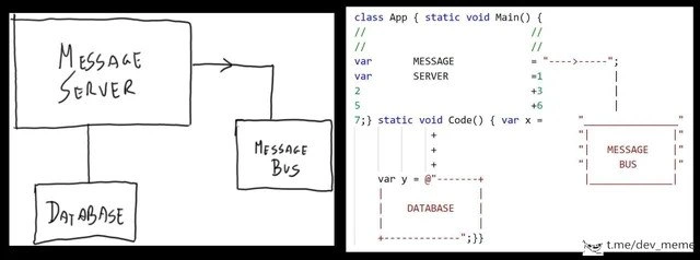
The meme shows a side-by-side of a system diagram and actual code that reproduces that diagram. The left side is a simple architecture diagram: basically a picture showing how different parts of a system connect (a Message Server connects to a Database and a Message Bus). The right side is a chunk of C# code that has been manipulated to look just like that diagram. The developer turned the source file into an ASCII art sketch pad. ASCII art means creating images or diagrams using the normal text characters you can type on a keyboard. For example, using +, -, |, and letters to draw boxes and arrows in a monospaced font. In this code, they literally spelled out "MESSAGE", "SERVER", "DATABASE", and "MESSAGE BUS" in the code and drew lines with characters to mimic the connections. We see lines starting with // (which are comments in C#) used to position text, plus signs + possibly representing corners or connections, and an arrow made of -> pointing to the MESSAGE BUS. They even used a multi-line string (in C#, the @"" syntax starts a verbatim string literal that can span multiple lines) to draw the DATABASE box below. The end result in the text editor is that the code’s text visually reproduces the original diagram. It’s like the developer carefully arranged letters, spaces, and symbols so that reading the code looks like looking at the whiteboard drawing, all while still being in a .cs file. Essentially, the code file contains an ascii_architecture_diagram of itself!
Why would someone do this? The idea was probably to make the code self-documenting. Self-documenting code is a programming principle where the code is written clearly enough (with good naming and structure) that it largely explains itself without needing separate documentation. In this case, the developer went for a very literal form of self-documentation: embedding the entire high-level design drawing into the code. The thought process might be, “If the diagram is right here in the code, anyone reading the code will immediately understand the whole system design without searching for a separate document.” It’s an attempt to have a single source of truth by keeping the design and code together. It also might stem from not wanting to use external diagram files or wikis – instead, everything is in the code repo. There’s a hint of pride or cleverness here: it’s a flashy way to say, “My code documentation lives in the code itself!” This trick can also be seen as a workaround if the developer didn’t want to use or didn’t have access to proper diagramming software. By using plain text and the programming language’s features (like comments and strings), they achieved a diagram right in their IDE. It’s a sort of hacky design document embedded in the source. At first glance, it’s actually pretty cool to see text art in a code file – it shows creativity and attention to detail in aligning everything. It certainly would surprise anyone doing a code walkthrough!
However, this is also a classic example of over-engineering something that should be simple. Instead of using a normal diagram in a document or a tool, the developer chose a very convoluted path. The joke here is that mixing a diagram directly into code is more trouble than it’s worth. It makes the actual program harder to read and change. Code is meant to be executed or at least define some logic – but these diagram lines are not real logic, they’re just comments or unused strings meant for humans. If another programmer needs to update the system design, they have to carefully move text around to redraw the ASCII lines, which is cumbersome. If the architecture changes (say we rename Message Bus to something else or add a new component), someone might forget to update this in-code diagram, causing confusion. In normal practice, we’d keep architecture diagrams in a separate documentation file or at least generate them automatically from source using a tool. By doing it manually inside the code, the developer has created extra work for themselves and others. It’s funny because it feels like someone drawing a pretty picture in the source code and expecting everyone to maintain that picture. It’s a diagram_in_code_comments taken to the extreme. This kind of documentation humor highlights how absurd it would be if everyone documented systems this way. In short, the code became a canvas for an ASCII art diagram – a neat party trick, but not a maintainable practice. It’s as if the developer tried to make the code both the machine and the instruction manual at once, like painting an instruction diagram onto the machine you’re building instead of printing it on paper. Clever? Maybe a little. Practical? Not really. That contrast is what makes us smirk at this situation.
Level 3: Hard-Coded Blueprint
In this meme, a developer has literally hard-coded an architecture diagram into a C# source file. The left panel is a hand-drawn architecture sketch: a big Message Server box points to a Message Bus and down to a Database. The right panel shows that same diagram painstakingly recreated with actual code and text characters. It’s as if the code editor became an Etch-A-Sketch, drawing boxes and arrows with characters. This mashup of documentation and implementation is both impressive and absurd. It’s the ultimate form of "self-documenting code" taken way too literally. Seasoned engineers see this and chuckle, recognizing a comical case of over-engineering. The developer effectively treated the source file as a design canvas, aligning // comments, plus signs, and string literals so the code itself visually mirrors the system’s blueprint. It’s a monument to over-engineering indeed, born from good intentions but raising eyebrows in any code review.
Why is this funny to experienced devs? Because it breaks the unwritten rules of code quality and clarity. Normally, an architecture diagram lives in a design document or wiki page – separate from the code. Embedding what should have been a design doc directly into the code is highly unorthodox. We strive for code that’s self-explanatory through clear structure and naming, not through ASCII sketches of the whole system in the middle of a class file! Here, the author mixed two different layers of concern: high-level system design and low-level code implementation. The result is a source file that doubles as a whiteboard drawing. This isn’t a standard Design Pattern or anything – it’s more like an ad-hoc diagram jammed into the codebase. The humor comes from the DeveloperHumor of seeing a practice we’re taught to avoid (cluttering code with elaborate comments or art) done to such an extreme that it actually outlines the whole system in-text. It’s the kind of thing you’d joke about in a Slack channel: “Hey, who needs Visio or Lucidchart when you have code?!”
From a senior perspective, we also recognize the hidden maintenance nightmare here. Code and documentation tend to drift apart over time – and this approach guarantees it. If the architecture changes, will the dev remember to update the ASCII art diagram in the code? Unlikely. Stale documentation is bad enough when it’s in Confluence; stale documentation embedded inside the code is even worse, because future maintainers might trust it, not realizing it’s outdated. It violates the Single Responsibility Principle in a tongue-in-cheek way: this class isn’t just running the app, it’s also acting as its own UML diagram. 😅 Imagine the next developer opening this file – instead of straightforward logic, they’re greeted by a text art installation of the system design. It’s funny, yes, but also painful to parse. One could say this is a self_documenting_misfire: the coder aimed for self-documentation, but overshot into self-parody. In professional environments, we have tools for design documentation and diagramming for a reason. Embedding the diagram directly in code bypasses proper diagramming tools (like UML diagrams or Markdown + Mermaid charts) and makes the code harder to work with. Yet, that’s exactly why it’s comedic: it’s a geeky DocumentationHumor showcase of doing something the hard way. We laugh because we’ve all met that overzealous coder who tries to be ultra-clever. In the end, the code is indeed self-documenting – maybe too self-documenting, turning a simple class into an art project. It’s an absurd illustration of the phrase “the code is the documentation” taken to an extreme, and it gets snickers from veteran engineers precisely because we know someone, somewhere, thought this was a brilliant idea (and we’re glad it’s not our codebase!).
Description
A two-panel meme contrasting a software architecture diagram with its literal implementation in code. The left panel displays a simple, hand-drawn diagram on a white background, featuring three boxes labeled 'MESSAGE SERVER', 'DATABASE', and 'MESSAGE BUS'. Arrows and lines connect them, showing the Message Server communicating with the Database and the Message Bus. The right panel shows the same architectural diagram meticulously recreated as ASCII art within a C# code snippet in a dark-themed editor. The class 'App' and methods 'Main' and 'Code' are used as a canvas, with comments, strings, and variable declarations forming the shapes and labels of the server, bus, and database. This meme humorously visualizes the concept of 'code as documentation' taken to an absurd extreme. It resonates with experienced engineers who appreciate both the elegance of well-defined architecture and the clever, if impractical, ways developers sometimes express ideas directly in the source code
Comments
7Comment deleted
Some architects use UML, others draw on a whiteboard. Then there are the 10x engineers who submit a PR with their architecture diagram directly in the main function, achieving perfect code-documentation parity at the cost of everyone's sanity during code review
Turned the architecture diagram into a multiline string so docs never drift - now every whitespace linter run counts as an infrastructure migration
The three stages of enterprise architecture: the pristine whiteboard diagram that gets you promoted, the actual code that barely resembles it, and the production system held together by environment variables and prayer - but at least the variable names match the boxes!
Ah yes, the classic enterprise architecture pattern: draw a beautiful message bus diagram in the design doc, then implement it as three hardcoded string variables and ASCII art in comments. The DATABASE variable being set to '=5' really captures that enterprise-grade configuration management we all aspire to. At least future archaeologists will appreciate the effort to preserve the original architecture diagram in the codebase - nothing says 'maintainable' quite like box-drawing characters in a static void Code() method. This is what happens when the architect leaves before implementation and the intern is told to 'just make it work by Friday.'
Because direct DB calls lack that essential 'eventual consistency' tax Java loves to impose
Whiteboard-driven development: the message bus is a string literal, the database is ASCII art, and the only event stream is the '+' key until the arrows line up
When your architecture lives inside Main, one dotnet format turns a refactor into a full re-architecture diff that triggers an ADR review